Armature timing and Aftermarket timing fixtures.
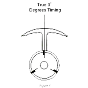
Armature Timing – For simplicity’s sake, think of the commutator as the “switching system” for turning the poles of the armature on and off in their function as electromagnets. “Armature timing” is the term used to describe the relationship, in degrees, of the segments of the commutator to the stacks or poles of the arm. As you can see in Figure 1, below, armature timing is expressed in degrees of advance from a base of zero at the nominal centerline of each stack leg. Looking at the com end of an armature, one with 0° of timing would have the leading edge of its com segment – or the trailing edge of its com slot(s) – lined up with the center of each stack leg. A common misconception is that the edge of the armature stack is used to determine armature timing. This is wrong, the stack edge has no bearing on armature timing at all. True timing is figured from the center of the stack leg (which is not visible in a finished armature).
The differences between one level of timing and another may appear slight, but slight is all it takes to make a major timing change at the com. Consider it this way: given a com diameter of .202″, one degree of timing at the comm is approximately .00178″ of its circumference (diameter * pi / 360). Put another way, a .5 mm pencil line is more than 11 “com degrees” wide or a common piece of computer paper .005 thick is 2.8 “com degrees” wide at the same diameter. The slots used in ProSlot comms are .014″ wide, in other words the slot itself is 7.8 “com degrees” wide.
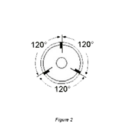
They are cut offset from the centerline of the comm. This insures that the leading edge of the comm segment is always on the shaft centerline no matter how wide the actual slot may be.
(see figure 2)
During manufacture we use a specially designed fixture that indexes the leading edge of the comm segment with the center of the armature blank leg. It is calibrated in 1 degree increments through 360 degrees of rotation. The comm is locked in the fixture head and the blank is placed in the indexer and rotated to the desired timing and the 2 components are pressed together in prefect alignment. The blank is then sent to the CNC machine for winding.
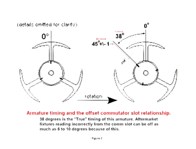
To my knowledge the aftermarket industry has yet to produce a fixture that takes into account the offset commutator slot and the commutator leading edge to blank leg center relationship. This accounts for the wildly inaccurate readings people are getting using these fixtures. Aftermarket
fixtures reading incorrectly from the comm slot can be off as much as 6 to 10 degrees because of this. (See figure 3)
Special Thanks to:
Dan De Bella
Frank Eubel